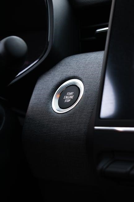
Understanding the Ignition Switch Wiring Diagram
An ignition switch wiring diagram is a schematic representation of the electrical connections controlling the vehicle’s ignition system, including power distribution to accessories and essential components.
It provides a visual guide for installing, troubleshooting, and repairing the ignition system, ensuring proper functionality of lights, radio, and other features powered by the ignition switch.
Role of the Ignition Switch in Vehicle Electrical Systems
The ignition switch serves as the central control point for a vehicle’s electrical systems, managing the distribution of power to essential components like the engine, lights, and accessories.
It acts as a gatekeeper, ensuring power flows only when the key is in the correct position, thereby preventing unauthorized use of the vehicle and protecting electrical circuits from damage.
By isolating the battery from the rest of the system when off, the ignition switch prevents parasitic drain and ensures electrical components activate only when intended, maintaining system efficiency and safety.
Its role is critical for proper vehicle operation, as it directly influences the functionality of systems tied to ignition, accessories, and starting mechanisms.
Key Components of an Ignition Switch
The ignition switch consists of several essential components, including terminals, wiring harnesses, and electrical contacts, which work together to control power distribution.
The switch features multiple terminals for connecting wires that supply power to various systems, such as the ignition coil, starter motor, and accessories like lights and radios.

The wiring harness acts as the backbone, routing power to designated circuits based on the switch’s position, ensuring proper functionality across different modes.
Electrical contacts within the switch ensure reliable connections, while the mechanical actuator provides the user interface for selecting operational modes like “OFF,” “RUN,” and “START.”
Together, these components enable the ignition switch to efficiently manage the vehicle’s electrical systems, ensuring safe and controlled operation.

How to Read an Ignition Switch Wiring Diagram
Reading an ignition switch wiring diagram involves identifying symbols, tracing connections, and understanding color codes to interpret how the switch controls power distribution in the vehicle.
Common Symbols and Terminology
Ignition switch wiring diagrams use standardized symbols to represent components such as switches, relays, and fuses. Common symbols include circles for switches and rectangular boxes for fuses. Terminology like “BAT” for battery, “IGN” for ignition, and “ACC” for accessories is frequently used to label wires and connections. Understanding these symbols and terms is essential for accurately interpreting the diagram; Additionally, color coding is often indicated, with colors like red for constant power and yellow for ignition-controlled circuits. Familiarity with these conventions ensures proper installation and troubleshooting of the ignition system. Always refer to the diagram’s legend for specific component representations and abbreviations.
Interpreting Wire Colors and Their Functions
Wire colors in an ignition switch wiring diagram indicate specific functions, ensuring consistency across installations. Red typically represents a constant power source, while yellow often signifies ignition-controlled power. Black wires usually denote ground connections, and white or gray wires may connect to accessories like lights or radios. Brown or orange wires might control functions like wipers or turn signals. Understanding these color codes is crucial for accurate wiring. Always refer to the diagram’s legend to confirm the color assignments, as variations can occur between manufacturers. Proper interpretation ensures safe and efficient connections, preventing electrical system malfunctions. Consistency in color coding simplifies troubleshooting and maintains system reliability.
Types of Ignition Switch Wiring Diagrams
Ignition switch wiring diagrams are categorized into universal and vehicle-specific types. Universal diagrams offer general wiring schemes adaptable to various vehicles, while vehicle-specific diagrams provide precise details for particular models. Additionally, modern and classic vehicle diagrams differ significantly, reflecting advancements in electrical systems and technology;
Universal vs. Vehicle-Specific Diagrams
Universal ignition switch wiring diagrams are designed to be adaptable across multiple vehicle types, providing a generalized layout of connections and components. These diagrams use standardized symbols and color coding, making them versatile for DIY repairs and general troubleshooting. Vehicle-specific diagrams, however, are tailored to particular models, offering precise wiring details unique to the vehicle’s electrical system. They include exact wire colors, connector positions, and specific functions, ensuring accurate installations and repairs. While universal diagrams are helpful for basic applications, vehicle-specific diagrams are essential for complex systems, reducing the risk of errors and ensuring compatibility with the vehicle’s unique configuration.
Differences in Wiring Diagrams for Modern and Classic Vehicles
Modern ignition switch wiring diagrams often incorporate advanced features like computer-controlled systems, CAN bus communication, and electronic control units (ECUs). These diagrams include detailed modules for fuel injection, anti-lock braking systems (ABS), and other modern conveniences. In contrast, classic vehicle diagrams are simpler, focusing on basic circuits for ignition, lighting, and accessories. Modern diagrams require understanding of advanced symbols and terminology, while classic diagrams rely on straightforward wire colors and connections. Additionally, modern vehicles may use multiplex wiring, reducing the number of wires but increasing complexity. Classic vehicles, however, use simpler, more direct wiring paths, making them easier for enthusiasts to work with without specialized tools.
Installation and Wiring Guidelines
Always refer to the ignition switch wiring diagram for specific instructions. Use appropriate tools and ensure correct wire connections to avoid electrical system damage or malfunctions.
Step-by-Step Guide to Wiring an Ignition Switch
- Disconnect the battery to ensure safety while working on the electrical system.
- Ground the ignition switch to the vehicle’s chassis to complete the circuit.
- Connect the battery wire (usually red) to the “BAT” terminal on the switch.
- Attach the ignition wire (commonly yellow or pink) to the “IGN” terminal.
- Link accessories like lights or radios to the “ACC” terminal using the appropriate wires.
- Test each position of the ignition switch to confirm proper functionality.
- Refer to the wiring diagram PDF for specific terminal locations and color coding.
Following these steps ensures a safe and correct installation of the ignition switch.
Importance of Colour Coding in Ignition Wiring
Colour coding in ignition wiring is essential for identifying wire functions and ensuring proper connections. Standardized colours like red for battery, yellow for ignition, and black for ground help avoid errors during installation or repairs.
- Colour coding enhances safety by preventing incorrect connections that could cause short circuits or electrical fires.
- It simplifies troubleshooting by allowing quick identification of wires responsible for specific functions.
- Referencing the wiring diagram PDF ensures accuracy, as colours may vary slightly between manufacturers or vehicle models.
Consistent colour coding across vehicles promotes efficiency and reduces confusion for technicians and DIY enthusiasts alike.
Troubleshooting Common Issues
Identify ignition switch problems by checking wire connections, battery power, and fuse conditions. Use the wiring diagram to trace circuits and locate faults efficiently.
Identifying Faults Using the Wiring Diagram
Using the ignition switch wiring diagram, you can systematically identify faults by cross-referencing symptoms with the circuit layout. Start by checking the wire connections and ensuring they match the diagram. Verify the power supply to the ignition switch and associated components. Use the diagram to trace the circuit path, isolating issues like open circuits or short circuits. Check for blown fuses or faulty relays indicated in the wiring layout. Refer to the color-coded wires to confirm connections to accessories, lights, and the starter motor. This methodical approach helps pinpoint malfunctions efficiently, ensuring accurate repairs and restoring proper ignition system functionality.
Common Problems and Solutions
Common issues with ignition switch wiring include faulty connections, worn-out wires, or incorrect installations. Symptoms may involve intermittent power loss or failure to start the engine. To resolve these, consult the wiring diagram to identify correct wire colors and connections. Replace damaged or corroded wires, and ensure all terminals are securely fastened. If the ignition switch itself is malfunctioning, refer to the diagram to bypass or replace it properly. Additionally, verify the circuit breaker and fuse statuses, as tripped breakers or blown fuses can mimic ignition switch failures. Regularly inspecting the wiring and connections can prevent such issues, ensuring reliable ignition system performance and safety.

Download and Usage of Ignition Switch Wiring Diagram PDF
Download reliable ignition switch wiring diagrams in PDF format from trusted automotive resources or manufacturer websites for accurate installation and troubleshooting guidance specific to your vehicle model.
Where to Find Reliable PDF Resources
Reliable ignition switch wiring diagram PDFs can be found on official manufacturer websites, automotive repair forums, and trusted DIY repair platforms. Many car brands, such as Ford and GM, provide detailed wiring diagrams specific to their models. Additionally, websites like AutoZone and O’Reilly Auto Parts often offer free access to wiring diagrams for various vehicles. Specialized forums and communities focused on car repairs are another excellent source, as members frequently share verified diagrams. Always ensure the PDF is compatible with your vehicle’s make and model for accuracy. Downloading from reputable sources guarantees high-quality, error-free diagrams tailored to your needs.
How to Use the PDF Diagram for DIY Repairs
Using an ignition switch wiring diagram PDF for DIY repairs involves cross-referencing the schematic with your vehicle’s electrical system. Start by identifying the components shown in the diagram, such as the ignition switch, battery, and accessories. Match the wire colors and terminal connections to ensure proper installation. Use the PDF to trace circuits and diagnose faults, such as open connections or short circuits. When replacing the ignition switch, refer to the diagram to connect wires accurately. This guide helps minimize errors and ensures your vehicle’s electrical systems function correctly after repairs.

Best Practices for Ignition Switch Wiring
Always use the correct tools and refer to the wiring diagram PDF for precise connections. Follow safety guidelines, ensure proper wire routing, and test the system after installation.
Safety Precautions When Working with Electrical Systems
When working with ignition switch wiring, always disconnect the battery to prevent accidental power surges. Use insulated tools to avoid electrical shocks. Ensure the ignition is in the “off” position before starting work. Refer to the wiring diagram PDF for accurate connections. Never touch live wires or components without proper grounding. Wear protective gear, including gloves and safety glasses. Avoid overloading circuits, as this can cause system failures. If unsure, consult a professional or the vehicle’s manual. Proper grounding and secure connections are critical to prevent malfunctions and ensure safety. Testing the system gradually after installation can help identify potential issues early. Always follow manufacturer guidelines for tools and materials.
Tools and Materials Needed for Installation
To install an ignition switch, you’ll need a multimeter for testing circuits, wire cutters and strippers for preparing wires, and a soldering iron for secure connections. Use high-quality 14 AWG wire for power supply and 16 AWG for accessories. Heat shrink tubing and electrical tape are essential for insulation. A wiring harness connector specific to your ignition switch is required for proper installation. Refer to the wiring diagram PDF for accurate connections. Additionally, a fuse kit and a ground wire ensure safe and reliable operation. Always use insulated tools to prevent electrical shocks. Proper tools and materials ensure a safe and professional installation.